Every few years, someone declares vibratory feeder bowls dead. A new technology comes along—vision-guided flex feeders, AI-powered bin picking, some slick demo at a trade show—and suddenly the conversation shifts to “the future of parts feeding.” And every time, vibratory feeders quietly keep doing what they’ve always done: orienting millions of parts per day, shift after shift, without complaint.
Here’s what’s actually happening on factory floors in 2026. It’s more interesting than the headlines suggest.
The Buzz Around Flexible Feeding (And What They’re Not Telling You)
Let’s give credit where it’s due. Flexible feeding systems—the ones that dump parts onto a flat surface, snap a photo with a vision camera, and let a robot pick what it sees—are impressive technology. They handle multiple part geometries without retooling. They’re great for low-volume, high-mix environments. And they look fantastic in a sales presentation.
But here’s what gets lost in the excitement: speed and simplicity still win in high-volume production.
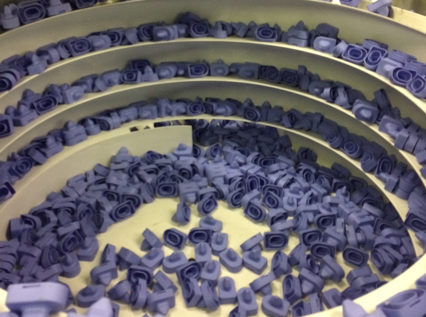
A well-tooled vibratory feeder bowl will orient and deliver parts at 30, 45, even 60+ parts per minute, all day long. No cameras to calibrate. No lighting to adjust. No software updates. The physics of vibration, gravity, and precision-machined tooling do the work. For manufacturers running dedicated lines—automotive clips, pharmaceutical caps, fasteners, electrical connectors—that kind of throughput and reliability isn’t just nice to have. It’s the whole ballgame.
Where Robotics and Vibratory Feeders Actually Meet
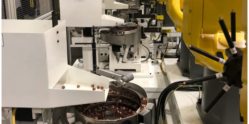
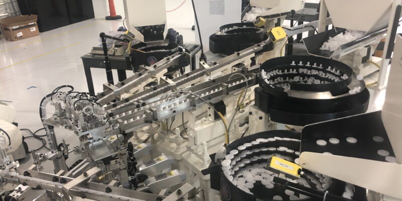
The real story in 2026 isn’t “robots vs. vibratory feeders.” It’s robots with vibratory feeders. And this is where things get genuinely exciting for manufacturers who are building or upgrading automated assembly cells.
Cobots need to be fed. The collaborative robot market has exploded—we’re looking at north of $11 billion globally, with over 210,000 units shipped in the last year alone. These robots are showing up in plants of every size, handling pick-and-place, assembly, inspection, and packaging. But a robot arm sitting in a work cell is useless without a reliable stream of correctly oriented parts arriving at its pickup point.
That’s the job of a parts feeder. And vibratory feeder bowls remain the most cost-effective, proven way to do it for dedicated part runs.
Here’s what a typical integrated cell looks like today:
- A vibratory feeder bowl orients and singulates parts from bulk
- An inline track queues parts and provides buffer storage
- A sensor (usually Keyence or similar) monitors part levels and triggers the bowl and hopper automatically
- A cobot or industrial robot picks oriented parts from the end of the track for assembly, packaging, or transfer
The feeder handles the messy, mechanical job of turning a bin of random parts into a single-file line of perfectly oriented components. The robot handles the precision placement downstream. Each does what it’s best at. No AI required.
Smart Sensors Are Making Vibratory Feeders Smarter
One of the quieter upgrades happening across the industry is the addition of smart sensor technology to traditional vibratory feeding systems. We’re not talking about ripping out proven equipment and replacing it with something untested. We’re talking about bolt-on intelligence.
Amplitude monitoring lets operators (and the system itself) track vibration levels in real time. If a bowl’s feed rate drifts—maybe the springs are wearing, maybe the part weight changed slightly between production runs—the system flags it before it becomes a line stoppage.
Automated level control uses sensors on the bowl and hopper to keep part flow consistent without anyone watching. The hopper feeds the bowl. The bowl feeds the track. The track feeds the robot. It all runs hands-free until the hopper needs a refill, at which point a stack light tells the operator. Simple, effective, reliable.
These aren’t flashy upgrades. They don’t make good LinkedIn posts. But they’re the kind of practical improvements that keep lines running at 95%+ uptime, which is what actually matters when you’re filling orders.
The Real Question Manufacturers Should Be Asking
When a plant engineer or automation integrator is spec’ing out a new line, the question shouldn’t be “vibratory feeder or flexible feeder?” in the abstract. It should be: What does this specific application actually need?
Choose a vibratory feeder bowl when:
- You’re running one part (or a small family of similar parts) at high volume
- Feed rates above 20-30 PPM are critical
- The part geometry is well-defined and unlikely to change frequently
- You need proven reliability with minimal operator intervention
- Budget matters (and it always matters)
Consider flexible feeding when:
- You’re running dozens of different parts through the same cell
- Batch sizes are small and changeovers are frequent
- Part geometries are complex or delicate enough that traditional tooling can’t handle them
- You’re already committed to vision-guided robotics in the cell
Most plants? They need both. Different lines, different requirements. The vibratory feeder bowls handle the bread-and-butter high-volume work. Flex feeders handle the specialty stuff. And increasingly, both feed into robotic work cells.
What We’re Seeing From Our Customers
At Feeding Concepts, we’ve been building custom vibratory feeders and parts feeding systems since 1989. We work with everyone from Tier 1 automotive suppliers to medical device manufacturers to consumer packaged goods companies. And here’s what the conversations sound like in 2026:
“We’re adding a cobot to an existing line and need a feeder that integrates with it.” This is the most common request we’re getting right now. A plant already has a robot or is buying one, and they need a vibratory feeder bowl designed specifically to present parts where the robot can pick them—right orientation, right position, right timing.
“Our old feeders work fine mechanically, but we want smarter controls.” Retrofitting existing vibratory feeders with modern sensors, variable-speed controllers, and PLC integration. The bowl tooling doesn’t change. The drive doesn’t change. But the system gets a brain.
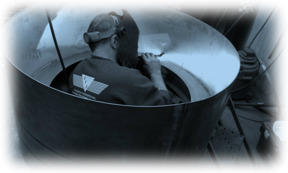
“We need a feeder that can handle a part nobody else wants to touch.” This is our favorite kind of challenge. Odd geometries, fragile materials, tight tolerances on orientation. The tooling inside a vibratory feeder bowl is where the real engineering happens, and it’s where decades of experience make the biggest difference.
The Bottom Line
Vibratory feeder bowls aren’t going anywhere. They’re not legacy technology waiting to be replaced. They’re mature technology that keeps getting better—smarter controls, tighter integration with robotics, better materials, quieter operation.
The factories of 2026 aren’t choosing between old and new. They’re combining the reliability of vibratory feeders with the flexibility of modern robotics, and the results are production lines that run faster, longer, and with less manual intervention than ever before.
If you’re building a new automated assembly cell, upgrading an existing line, or just trying to figure out how to get parts from a bin to a robot without losing your mind, we’d love to talk. That’s literally what we do.
Feeding Concepts has been designing and manufacturing custom vibratory feeders and parts feeding systems in Noblesville, Indiana since 1989. We build solutions for automotive, medical, pharmaceutical, food, and consumer goods manufacturers across North America. Contact us to discuss your application.